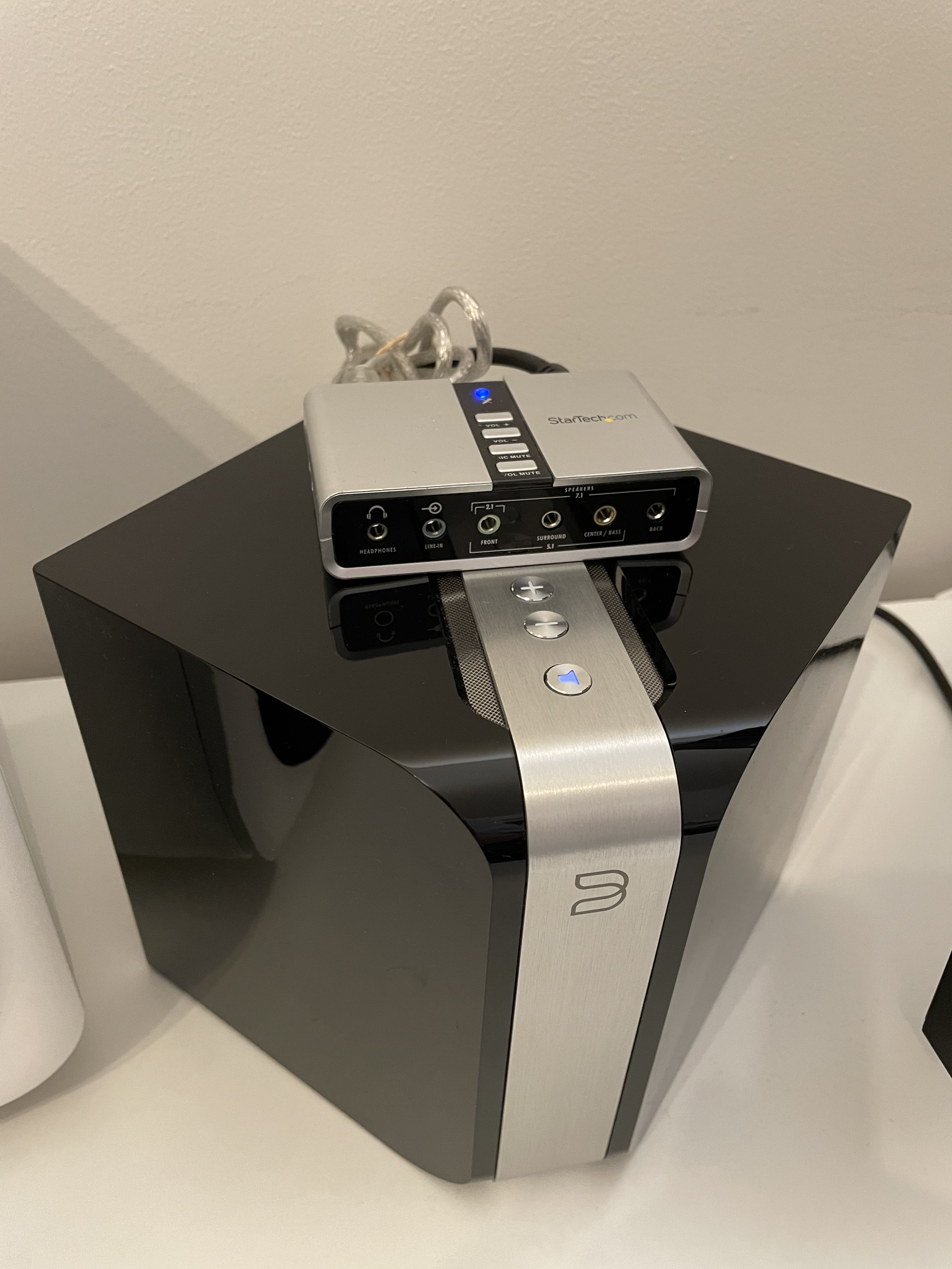
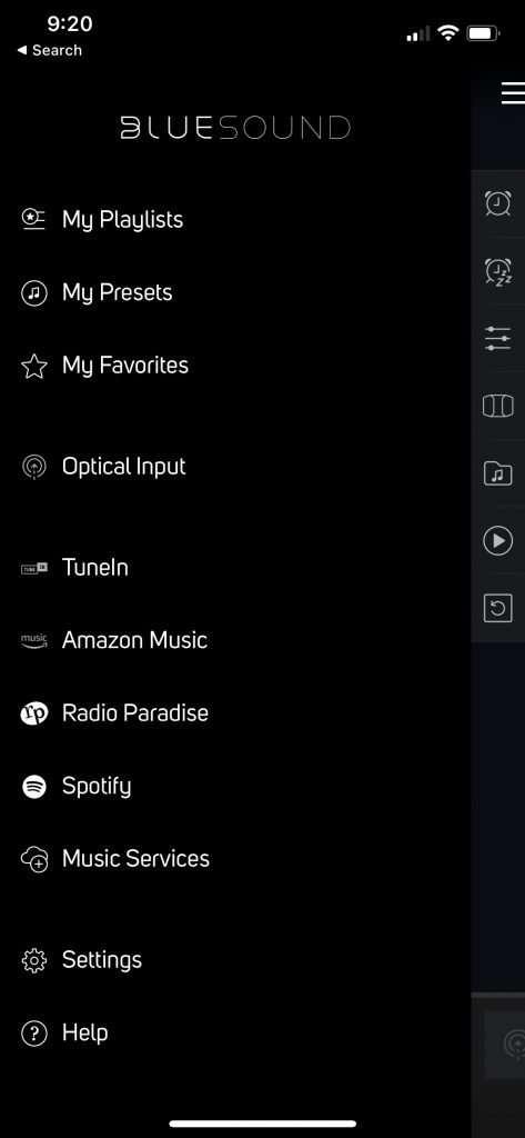
The Bluesound Powernode N150 is an IoT “super integrated” HiFi amplifier. This device is combination Streamer, DAC, Preamp and Power Amplifier. Utilizing the mobile and desktop apps one can directly stream Spotify, Amazon Music, TuneIn Radio etc.
One of the biggest downsides of this device is the lack of inputs besides the built-in streaming functionality (an issue mostly solved in newer, more expensive Powernode models). Luckily, there is a USB port in the back but unfortunately out-of-the-box this USB port only really supports a bluetooth dongle. It does not support a USB DAC or other peripherals, that is, without modification.
Internally the Powernode utilizes an ARM board running Linux and some custom Perl scripts. This means with root access and some modifications we can get other USB devices working with the available port.
In my case I used a StarTech 7.1 USB External Sound card (ICUSBAUDIO7D). These are pretty generic, I believe most of these 7.1 USB sound cards utilize the same C-Media CM6206 chipset. With some adjustments other cards will likely work as well.
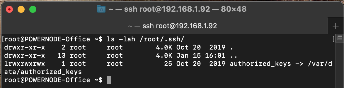
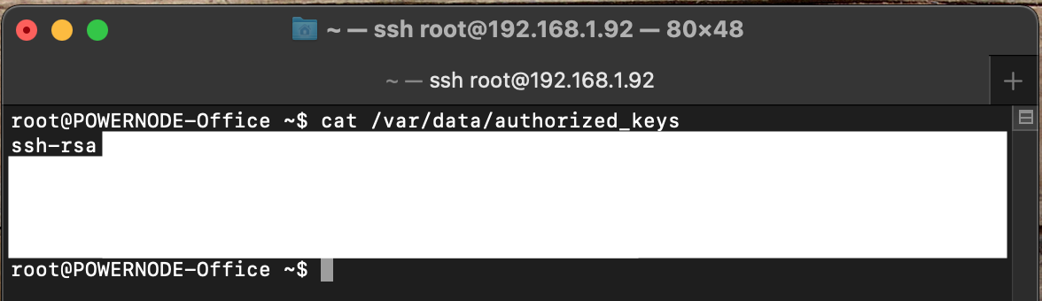
The first step is getting root on the device. One method is described here https://rot256.dev/post/bluesound-powernode/. There a definitely other methods to root this device, but I have found that one to be pretty reliable. Once root access is acquired, it is helpful to set up persistent access. This can be achieved by adding SSH keys to the Powernode at /var/data/authorized_keys. This is helpfully already symlinked to /root/.ssh/authorized_keys.
That /var/data path is an important one. The root filesystem is by default mounted read-only. When a firmware update is applied, the root filesystem is overwritten. The manufacturer uses /var/data as non-volatile storage for settings, volume states etc.
When firmware updates are applied, our modifications will be lost. If you plan to update your firmware, be sure to keep copies of these modification somewhere you can easily re-apply them. Note: at the top of the sovi_info.xml file that we will be modifying there is a “git” version number and “rootfs” date that are updated for every new firmware. These will also need to be updated in your modified files to work properly (and avoid issues with the update process).
Now that we have pivoted from our initial access to the persistent SSH session the rest of the work becomes easier. The primary file that needs modification is /etc/sovi_info.xml. This file appears to be where the manufacturer customizes the BluOS firmware to match the feature sets of their various products (and 3 party products they license the firmware to). In our case, for optical input, we are going to need to add a <capture> device entry.
First we need to grab a copy of the current sovi.info.xml. To do this I used scp to pull the file to my local machine:
scp root@192.168.1.92:/etc/sovi_info.xml sovi_info.xmlNow add the capture device to the config file. This should go right after the <bt>bluez</bt> line:
<capture>
	<device id="input0" name="{OPTICAL_INPUT}"
		type="spdif"
		hw="hw:1,0" format="S16_LE" channels="2" rate="48000"/>
</capture>
This modification is creating an input labeled “Optical Input” which maps to alsa audio card 1 device 0 (audio card 0 will be the internal audio device where streams and things are played). We set the SPDIF word length to 16 bit and sample rate to 48khz. Note: These SPDIF settings are now statically set, meaning the source must always output with these settings as well. In my case I manually configured the SPDIF output on Windows.
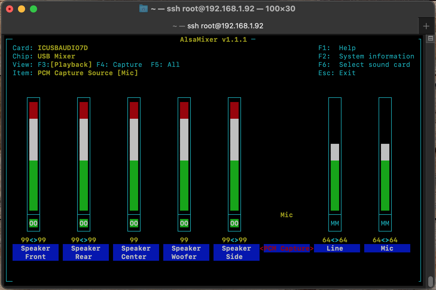
During experimentation I found one other issue. By default when the driver loads for the StarTech USB sound card, the “PCM Capture” toggle is set to “Mic”. For the optical input to work, this needs to be set to “IEC958 IN”. Changing this in ALSA mixer isn’t hard, but every time the device rebooted, I would need to SSH in and manually correct this.
To fix this, we also need to add an ALSA state file to sovi_info.xml. We’ll add this right below the existing <state file… line
<state file="asound.state.startech" card="1"/>Don’t worry about the asound.state.startech file itself, we will generate that later.
To do any modifications of the root filesystem, we need to first remount it read/write. This is easily enough done by SSHing into the Powernode and running:
mount -o remount,rw /dev/root /Next we need to upload the modified sovi_info.xml. On the host we run:
scp sovi_info.xml root@192.168.1.92:/etc/sovi_info.xmlNow we need to configure that asound state file. With the USB soundcard plugged in we want to manually configure the “PCM Capture” to “IEC958 IN”.
amixer -c ICUSBAUDIO7D set 'PCM Capture Source' 'IEC958 In'Now save the state:
alsactl --file /etc/asound/asound.state.startech storeWe should now be able to reboot and test the Optical Input:
rebootAs previously stated, set your source output to 16bit/48khz and obviously make sure the Toslink is plugged in 😉 Then play the test audio of your choice.
Jump in the BluOS app, select the Powernode, and you should be able to see and select the “Optical Input” from the hamburger menu.
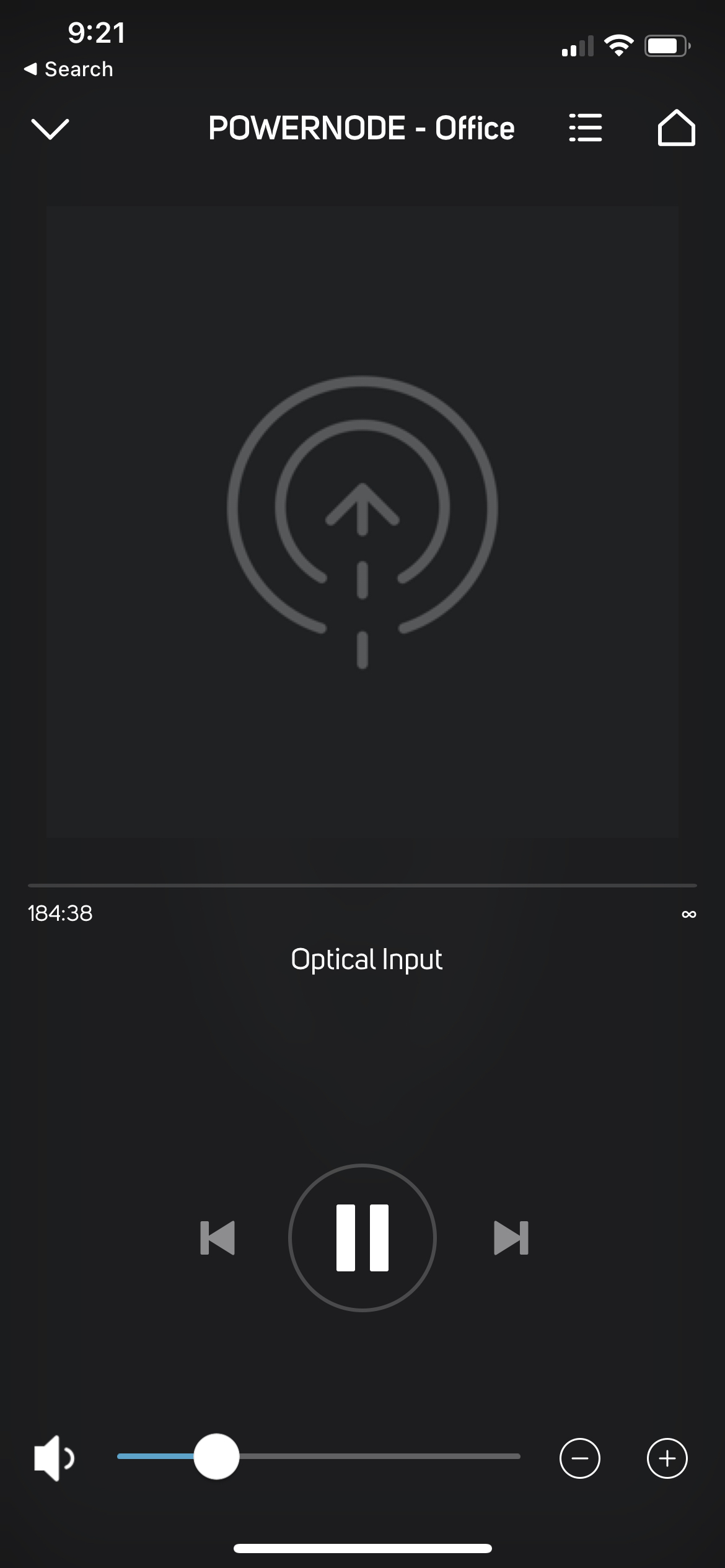
If you did everything right, the music should be playing!
Modification Backup/Restore for Firmware Updates
As stated above, the rootfs is overwritten during updates. Luckily the changes to /var/data are retained. Therefore the USB DAC mods will be lost (/etc/sovi_info.xml and /etc/asound/asound.state.startech will be gone) but our root access should remain (/var/data/authorized_keys should be retained). Keeping a local copy of both of our USB DAC mod files handy is a good idea.
After an update one simply needs to update some values in sovi_info.xml before recopying the files to the Powernode. After the update is complete SSH back into the Powernode and grab the new values:
cat /etc/sovi_info.xmlFrom there copy the values from <git></git> and <rootfs></rootfs> and update them in our modified sovi_info.xml
Then simply reupload the files with scp and reboot the Powernode. As of this posting, this method has worked. In the future with other updates, that may not remain true!


